Quackenbush Air Guns
9am-6pm Central time. No
Sunday calls!!
Home
In The Shop
These pictures have been converted to thumbnails for the
convenience of those using dial up internet. Click on the photo to enlarge
it.
Additional information, Paper Tools for Making
Airguns, added 1/10/05
Screw thread defining added 9/4/05
One of the purposes for In The Shop is to show
the manufacturing process. There are people who do not understand
manufacturing and believe that to have interchangeable parts, you would need to
have a sloppy fit. If you believe this, it puts you in the same group that
still believe that the earth is flat. That is what precision measurements are for. You
can gauge a part to the most miniscule amount so that parts will mate with no
interference, yet be so close in tolerance that there is no play. That's
why an aspiring machinist needs to know how to properly use micrometers, thread
micrometers, dial gauges and gauge blocks for precision measurements.
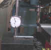
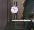
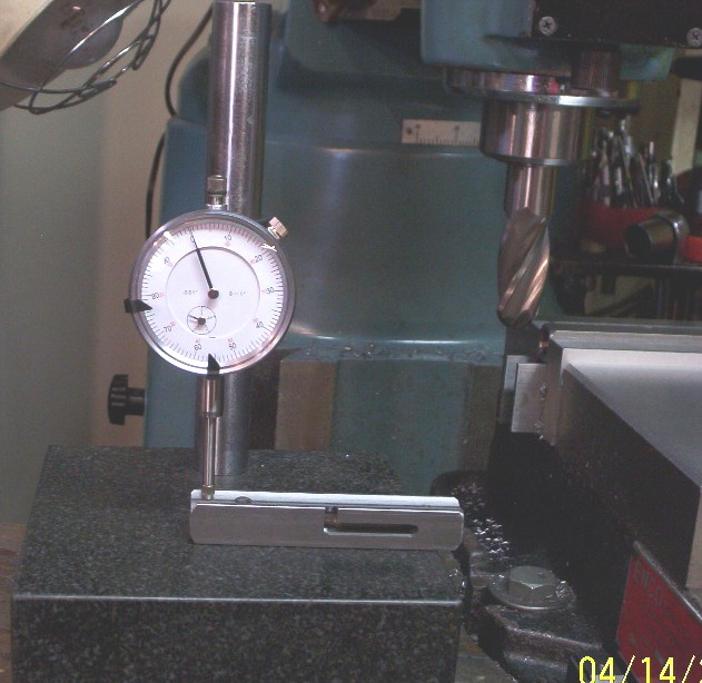
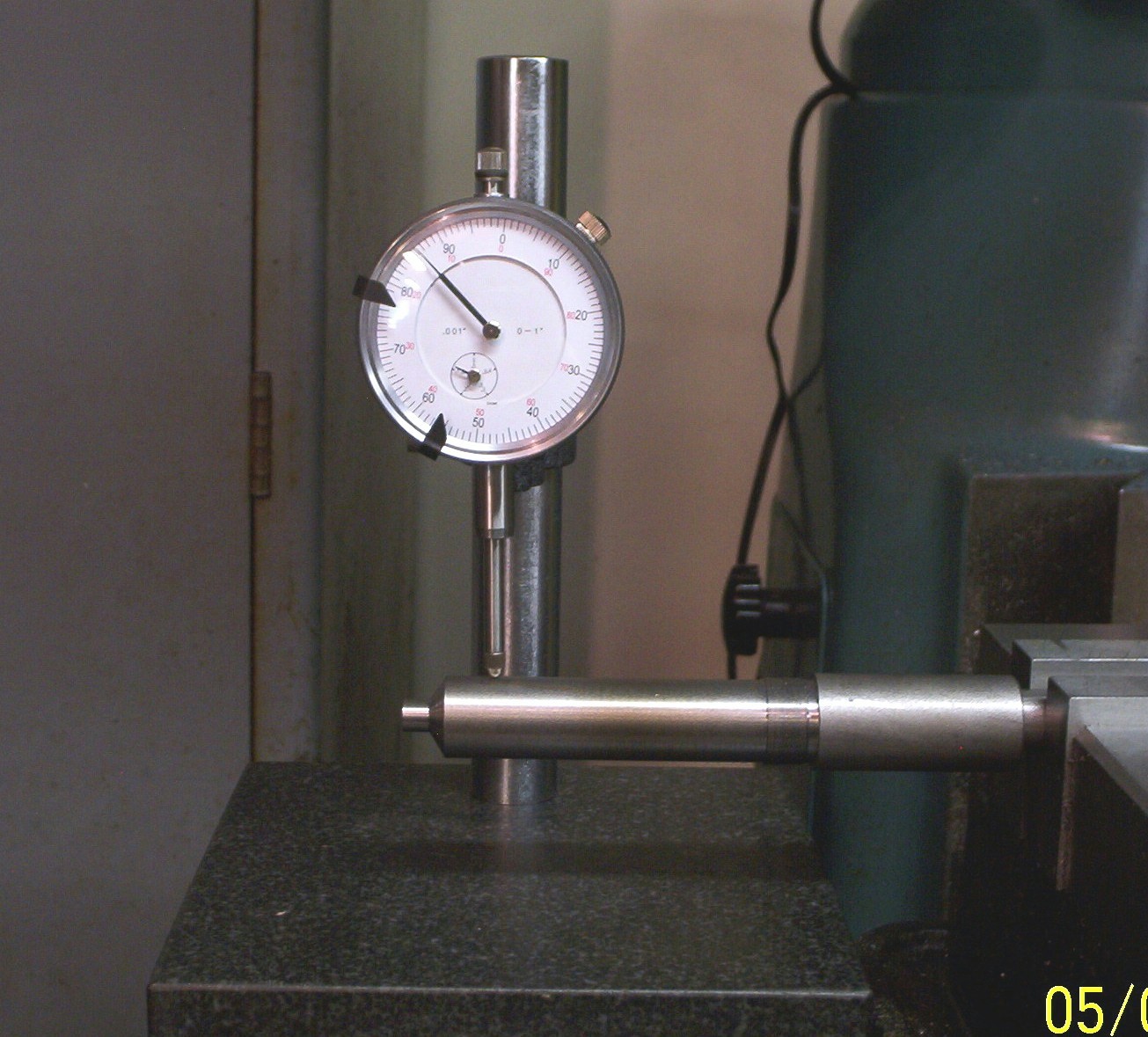
To be sure that the radius cut, on the bottom of the Crosman 2240 steel
breech, is correct, and not tapered, it is inspected. To make sure it's
not a tapered cut, which would make the breech sit at an angle, the breech is
measured at each end to check the machining set up. After the first piece
is milled it's placed under the dial gauge and gauge is zeroed at the contact
point at that end. The part is then measured at the other end. If
there was any difference in the height, the dial gauge would show how many
thousandths high to the right of where the needle is now (zero). If it was
low, it would show the amount to the left. Once this gauge procedure is
set up, parts can be checked in only a few seconds. If a chip, or
something, got under the part, or in the set up, it would quickly be found and
corrected, making sure that the parts continue to be machined correctly.
 click
on photos to enlarge
click
on photos to enlarge
Hardness testing: after heat treating to make wear parts harder and/or
tougher, the tester confirms that the job was done correctly.
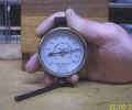
Durometer, used to test the resiliency of pliable materials. I use a
durometer in the shop to verify that the materials sent to me, by the supplier,
are the ones that were specified. Materials ordered, such as 'O' rings
or valve and seal material, have a performance requirement, and if the wrong
material is substituted you're looking for trouble. So, by testing, you
can prevent it.
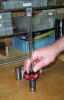
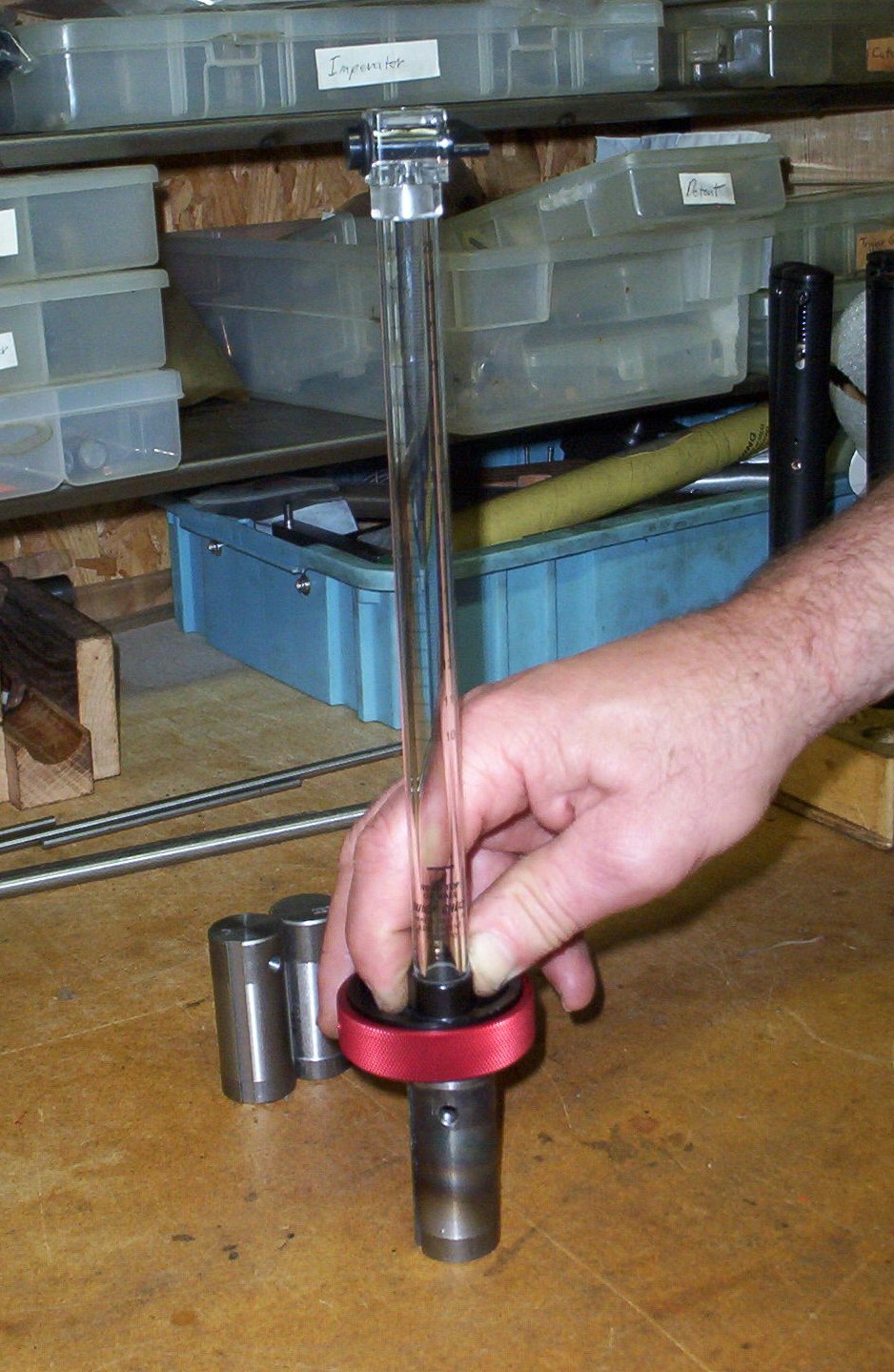
Gauging wall thickness to make sure that it is uniform. I make many
parts out of solid stock rather than tubing, such as this pictured CO2 bulk
tank. It's deep drilled from one end, and to make sure the drill didn't
wander, which would make one side thick and the other side thin, it is
gauged. The part is inserted over an anvil, the dial gauge is set and when
the part is rotated around the anvil the dial gauge indicates any variation in
thickness.
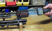
Trigger pull is tested to make sure that it is not too heavy, which would
disturb aim, or too light, that would make it unpredictable.
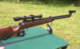
Collimator: to align the scope with the center of the bore. A collimator
is close, but not perfect so you still shoot it to get the fine
adjustment.
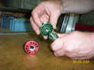
Thread ring gauges are used to verify that the threads meet industry
standard. The green "go" gauge has to go on to the part so that
you know that the thread is not too large. The red "no go" gauge
can't go onto the threaded part more than a turn or so, so you know that the
thread is not too small. The hardened steel center section of the gauge
has been ground to the correct pitch and thread shape, so that unless this is
correct on the part that you're making, the "go" gauge wouldn't fit.
By making threads to industry standards, a part made the other side of
the world or last century or next century will match and mate up. This is
the principle that modern manufacturing is based on, the interchangeability of
parts. I've made parts for aircraft this year that, when sent to the
customer, went perfectly into the assembly that was made in 1941.
Thread micrometer: Ring gauges are expensive, a "go" and "no
go" pair can cost $200, so on a part that is made in lesser quantities you
can verify the thread with a thread micrometer. A thread micrometer,
combined with a self opening die head with its micrometer like adjustments of
the thread depth, allows you to make the near perfect thread.
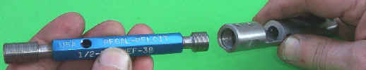
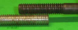
A thread plug gauge is used for checking internal threads. The short
section, pictured at the barrel thread of a breech, is the no-go, it should not
enter the thread. If the no-go entered, it would mean that the thread is
too large and wouldn't have enough holding capacity to keep the barrel snug in
the breech. The longer section, on the left hand side, is the
"go" side and should go into the threaded section its full
length. This lets you know that the thread is correctly machined. By
using modern manufacturing process, I can thread all the breeches to the
national standard and I can make the barrel thread any time later and I know
they're going to go together properly. No fitting, no reworking, no
sloppiness. One part fits another, just like it should be.
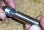
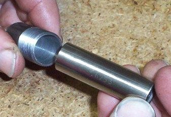
Plug gauge for checking size of internal holes. This plug gauge is
hardened and ground to be exactly .6253 at 72 degrees. On this job
application, the hole is to be .625, minus nothing, plus .0002. If you click on
the thumbnail photo and enlarge it you'll see the gauge is marked .6253, which
is .0001 larger than the allowed tolerance. So if this gauge enters, the
hole is too big and the part is rejected. One of the difficulties of
measuring bored or reamed holes, is that they may not be perfectly round; they
may be oval or lobed (like a clover leaf). If you were to measure a lobed
hole, you wouldn't detect it with just a telescoping gauge, because the gauge
would be on the high side of one lobe and the low side of another. If you
measured it in another position you could be just the opposite. So the
measurement would say it was good, but it's actually undersize. Using a
precision ground, round plug you check to see if the hole is truly round.
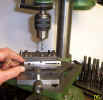
Drill fixture: when you're making many of the same parts a drill fixture
is most economical. After the initial time of making the fixture, the work
is done by inexpensive ($50.) drill presses. The drill fixture
clamps the part against locating surfaces so each part is held in the same
way. Hardened steel drill bushings are accurately located at the spots to
be drilled. Now that the part is held securely, and the drill bushings
will guide the drill to the exact spot, each different size drill used in the
process is in a separate drill press. Drilling this steel breech for the
22xx Crosman pistols used 3 different drill sizes, so I have 3 drill presses
lined up in a row, and the fixture is moved from drill press to drill
press. Since all the holes are drilled in one clamping, all the holes are
correct in relationship to each other.
This fixture has more than 3 bushings in it because I can turn the part
on its side and pre-drill for the bolt slot. The photo, on the right,
shows the hole already drilled.

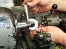
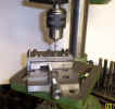
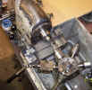
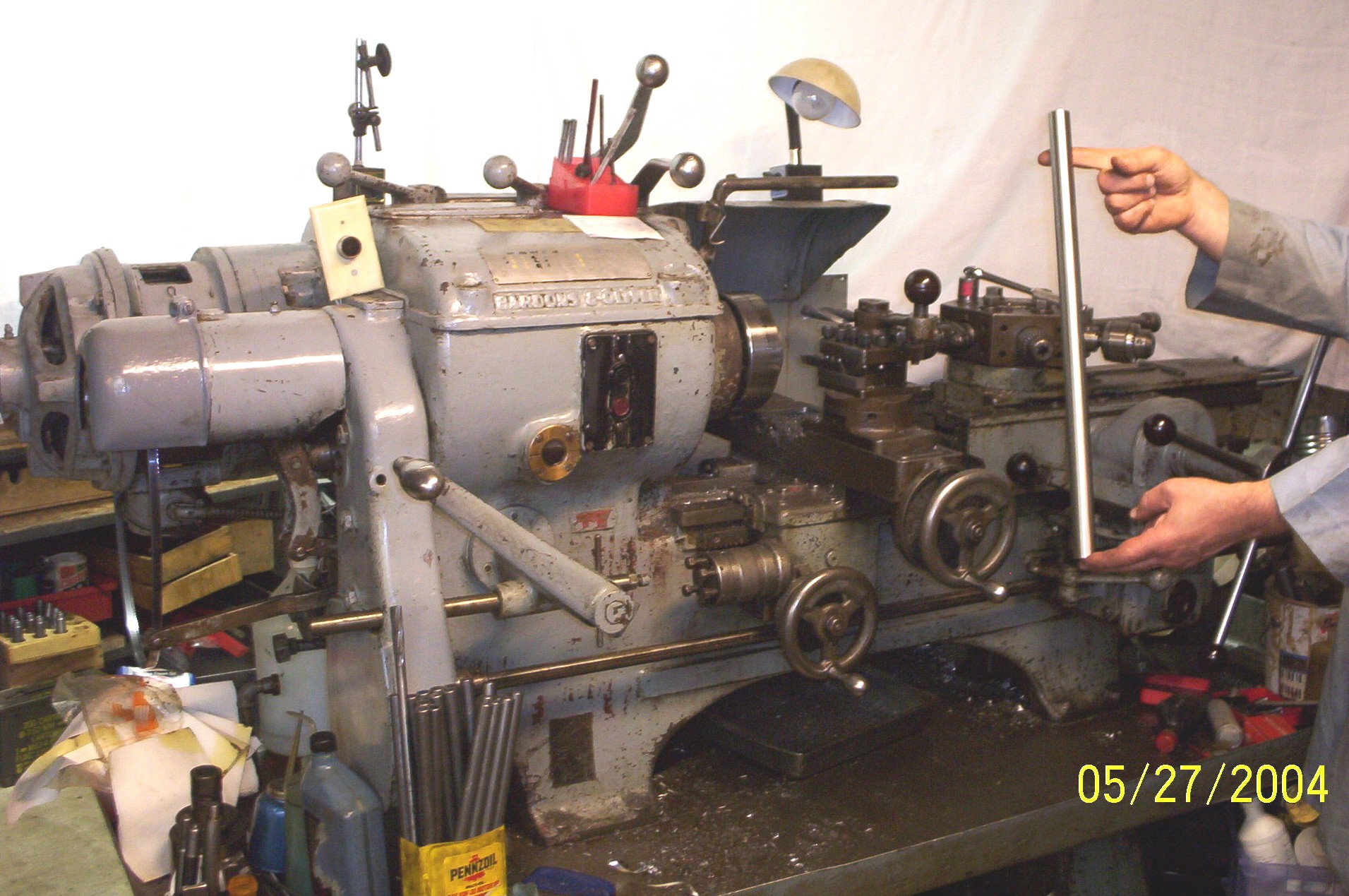
Turret lathe: This 3800 lb. WWII veteran was made in 1942. These are
the type of machines that helped to win the war. They made the parts for
tanks, jeeps, airplanes and ships. A turret lathe is still viable
today. I have a CNC 3 axis vertical mill that's used for profiling, but
for simpler operations the turret lathe is faster and much less expensive than a
CNC lathe. An example is an airgun reservoir tube. The tube is held
in a non-marring collet. The tube has to be faced,
counter bored for an 'O' ring seat, reamed to thread size, and threaded.
On the turret lathe
I can set up the tooling: a stock stop in the turret sets the work to the same
place every time; a tool bit in the cross slide faces the end of the tube; from
the turret, a counter bore makes the 'O' ring seat; the
next tool in the turret rotation reams the tube to the proper diameter for
threading (the picture shows the turret in this position, with the reamer about
to enter the part); and then a tap is put
into the end of the tube, the tap is held in a floating self releasing holder so
that when the tap reaches the preset depth, it releases from the drive and no
longer threads. The spindle is reversed and the tap is backed out of the
tube. The collet is released and the part is reversed (the machine does
not have to be stopped to do this) and the same work is done on the other end of
the tube. To do this work on one tube takes about 2 minutes. Setting
up the machine, machining 100 tubes and clean up when done, takes a little over
4 hours.
Ensuring quality parts is a process of checking and double checking every
process that you do. For reservoir tubes, the machine is set up and after
the first part is made the machine is shut off and the part goes to be pressure
tested. The ends are capped and then it's pressurized with the hydraulic
pump, pictured further below on this page. This way if you have bad steel
tubing it's discovered right away, not after making 50 pieces or so, that may
have to be scrapped. I've never had any bad tubing. I've never had a
failure. But you still have to test. Even if you are certain that
there are no problems, you still test. And then you even test the last
piece that comes off the machine. You can only get in trouble if you
disregard proper procedures.
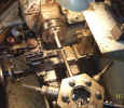
This picture shows the set up for machining a valve body.
The machined part is held in a precision collet that has less than .0002 total
indicator run out (you will see this abbreviated as TIR on blueprints and
drawings). There is a depth stop inside the collet, so the machined part
is in the same position every time. Consistency is what makes for
accuracy, and I'm explaining how that consistency comes about.
So the part is held in the same position, radially and axially from part to
part. Once a part is placed in the collet and clamped, all the operations
are done in one clamping. This way everything is in the correct
relationship to each other.
The photo shows the valve body ready to be drilled. The tool to the right
of the drill is a spotter that creates the center for the drill. The tool
to the left of the drill bores the inside of the valve body. And the next
tool (the turret revolves clockwise from this top view) cuts the valve
seat. The tools in the turret are set for the size they are to make, and
then have stops so they come to the same end position each time. So the
tools make the same cut, piece after piece. The only variation would be
after thousands of parts the amount of wear of the tool bit's cutting edge.
There are two tools in the cross slide. The tool on the right cuts a 45
degree angle on the end of the part, in preparation for threading. The
tool on the left cuts the 'O' ring groove.
The summary is that six machining operations are done to a work piece, in one
clamping, so all the cuts are done in the correct radial relation to one
another; which is what makes a good, accurate part. The valve's bore is in
line with the valve seat, which is also in line with the valve passage (having
all been done together). The 'O' ring groove is the same depth on all
sides, concentric with the valve body's bore.
The inception of turret lathes was in the mid-1800's. Definitely not new
technology, but refined technology. It is still used today in another
form. Most computer operated machines still have turrets or tools
slides, taken from turret lathe operation. They just took the human
operator out and put a computer in the operator's place. For short
productions runs of parts, I use turret lathes for amounts of 25-100 parts at a
time. Once I have all the tools set (with experience it takes less time
than programming a computer operated machine), I just keep on putting in steel
stock and continue to make consistently accurate parts, from part to part.
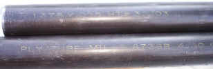
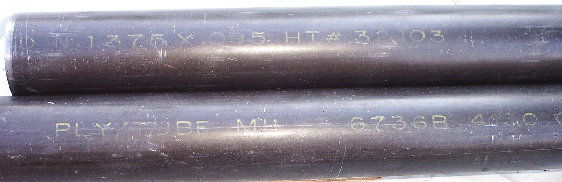
Materials, such as this tubing, have identification (not all of it is
discernable in this photo) such as: manufacturer, size, SAE number of its alloy,
and its heat number which identifies the lot in which it was made. When I
buy tubing I want to see the ink mark of a U.S. manufacturer (in this case,
Plymouth tube, abbreviated PLY.) Most imported tube has no markings on it
at all, so you have no way to truly confirm everything listed above.
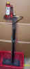
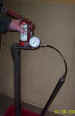
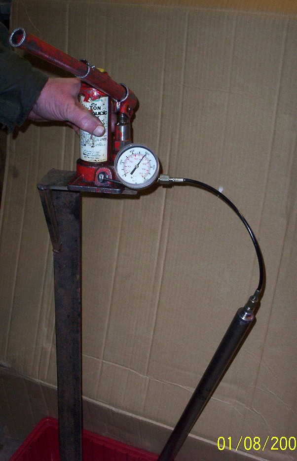
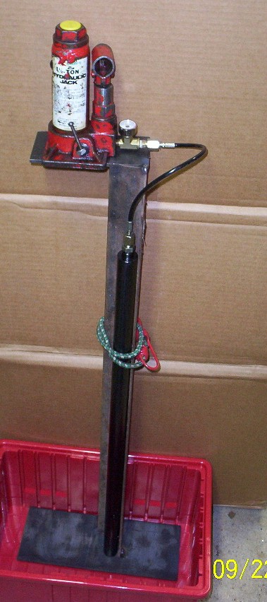
To pressure test airgun reservoirs I built this test cell in 1994, and with
minor modifications it still works today. The ram of the hydraulic jack is
removed and the pressure passage is plugged. The pressure is tapped off
the side of the pump with a flex hose to compensate for different reservoir
lengths. The area where the ram once was becomes a reservoir for the
soluble oil. I use soluble oil because the eventual drips and spills are
so much easier to clean up.
The reservoirs I use are good to 9000 psi before yield, but you don't test every
gun to where you damage it. I pressurize the gun to 6000 psi, which is
twice its normal working pressure, and hold it there for 24 hours; if there's no
pressure drop in that time then it passes.
Paper
Tools for Making Airguns
 click on picture to enlarge
Dimensioning
Every
machinist has an idea of the part they’re going to make.
A machinist also has a plan of how to make the part.
This may be as simple as a sketch on the back of a napkin (from a
conversation at lunch), to a full dimensioned CAD file.
A
machinist would pick the exact spot to drill a hole and then all the subsequent
parts, with the matching hole, would all mate up perfectly. The opposite is, without planning, you would put the hole
approximately where you think it should be and then make all the mating parts to
fit where that hole is at, which would entail more work.
Better planning means less time playing around trying to hand fit parts.
Not
using a plan, making a sketch or drawing with dimensions, is going back before
Eli Whitney, which is so last, last century.
You may have heard people tell you that their watch is polished or
jeweled in areas that you can’t even see.
In the era of when labor was cheap and materials were expensive, this was
a way for a watchmaker to say that his timepiece was better.
What was done in no way made it keep time better or changed its
durability or outward appearance. But
it gave the pompous something to brag about.
How much respect do you think you would give somebody if they were
bragging that they paid needlessly more money for an item, because the item was
made pre-Eli Whitney? The
knowledgeable know this is only the airing of the uninformed, but the gullible
still fall for it.
Metallurgy
Choosing
the right stuff. If you were to
make an airgun how would you know that you’re building it correctly?
Is it safe? Is it durable,
without being overbuilt to the point of being clunky?
This is when you decide which materials to use for each of the parts, or
verify that the material that you want to use will do the job as you want it to.
Will
the steel that you want to use work, as it comes from the supplier?
Does it need to be heat-treated? What
is its corrosion resistance? Is it
compatible with its surrounding materials?
Is
it suitable to be fabricated as you intend?
Can it be worked cold or does it have cold-shortness?
If you heated it to work it, would you destroy its strength?
Does it machine readily? Will
it yield a smooth finished surface? All
questions you could answer by cut and try experimentation, which is a lot of
work and a lot of trials. Or, just
go look it up and do it right the first time.
Machinery
Handbook (Standards)
Airguns
are held together by threaded parts. Standards
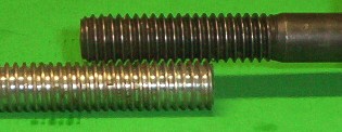
of threads by thread depth: the amount of engagement of the mating parts.
On some imported airguns, I have seen the engagement of the threads being
as little as 55%. These guns have
only held together because they’re CO2 guns.
There’s no more or less work to make a full strength thread than just
picking the correct size of the mating parts.
In this case, the size of the reservoir tube was too large for the thread
pitch chosen, reducing the amount of engagement.
The correction would have been to use a thicker walled tube and ream the
area to be threaded to size, or use a different thread pitch.
Brass
is not as strong as steel, so if you’re going to use a brass end you would use
fewer threads per inch so that the width of the root of the thread is wider, so
that it would be stronger. Using
brass rather than steel would require you to use a “coarser” thread, which
means you need a smaller threaded hole. This
would necessitate a different reservoir tube inside diameter, than if you were
using a steel end. So you need a
thicker walled tube, not to hold more pressure, but because of the requirement
of the brass threads being deeper and wider.
A
different thread configuration would be needed for each of the following
materials: aluminum, brass, mild steel and alloy steel.
For alloy steel it would use finer threads than the others, but care must
be taken because finer threads require closer attention to the thread O.D. and
the mating part I.D. A .005
thousandths too large a tapped hole, could reduce the thread strength by 40%.
Without a reference, you may not know this and make a part under strength
for the requirement.
Strength of
Materials
There
are custom made airguns that have a reservoir tube that would be rated at
4500psi max. So, you say, you’re
only filling the gun to 3000psi. To
look at this from an engineering point of view, it is not a question of fill
pressure, but the total stress (load) on the reservoir tube. As a stress factor,
this reservoir is already up to 2/3 of its strength. The 1/3 more is not enough safety factor.
1500psi is ½ of the fill pressure.
The safety factor for this would be 2 to 3 times the fill pressure.
If the reservoir was struck on a metal doorframe, the edge of a bench or
dropped, the extra stress induced at that location would be above the strength
limit of the total stress that the steel could take, and it would rupture at
that locale.
There
is overlap in making an airgun in the strength of materials and the metallurgy
of it and the sizes of the pieces to be put together. All of the information in the books above comes together so
that you make an item that won’t break readily or wear out prematurely,
without being something from the “locomotive” age where size and weight
didn’t matter.
Your
mind is your primary tool; don’t starve it for knowledge. These four books are just a sampling of some of the paper
tools you can use to make a better airgun.
Screw Threads; for Airguns & Life
Fasteners (screws, nuts & bolts) hold most of what we
know in airguns and life together. The
following is what I explain to my students how screw threads are described.
Screw threads have two descriptions.
One is its diameter, measured to the height of the threads.
The other is how many threads per inch.
Or, in metric use, the pitch of the threads that is the measurement from
one crest to the next.
The diameter, the outside size of the fastener, measured
fractionally for the inch system and by millimeters for the metric system has an
exception in the inch system. Under
a quarter inch diameter the inch system uses fractional and number sizes.
Here’s a list of the number sizes with the nominal standard size of the
screw:
#3 would be
.097 diameter
#4
.110
#5
.122
#6
.135
#8
.160
#10
.187
#12
.215
#14
.240
A number size screw, written by diameter and thread pitch, would be 8-32;
8 being the decimal equivalent and 32 being the number of threads per inch.
Screws are not the full dimension of their description.
An example is a 3/8-diameter thread will not measure exactly .375, but will be
some thousandths smaller. This is
because the sharp “V” of the thread has been eliminated.
There’s no strength in the thin crest of the “V” and this very thin
section could be damaged in handling.
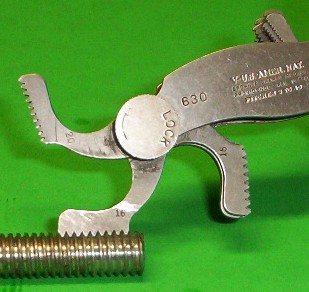
To determine the number of threads per inch, a machine shop
would use a thread pitch gauge. The
gauge has multiple blades, each with a different thread pitch on it, and using
it like a comb you use the blade that fits the thread. When you find the number of threads per inch, a fractional screw size
would be written: diameter-threads per inch. Example: 1/2-20, 1/2 (inch) being
the diameter and 20 threads per inch.

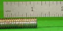
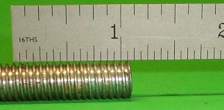
Most hobbyists don’t have a thread pitch gauge, so you
can use a scale. You can count how
many thread crests are in an inch. If
the fastener is short, measure how many in a quarter inch, then multiply by 4.
Another method of determining the thread pitch is to use a
known thread on a screw or bolt, like you would use a gauge.
An example is: if you had a 10-32 screw, you can use it to check any other
32-pitch thread, such as ¼-32 or ½-32, or any other 32 thread per inch
screw.
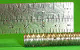
Metric fasteners can be measured as above, but the metric
description uses the distance between thread crest to thread crest.
When using a scale the thread may be finer than the graduations on your
scale. So count how many threads
are in a centimeter and divide by 10. Or,
if the screw is shorter than a centimeter, count the amount in half a centimeter
and divide by 5. The screw size would be written diameter in
millimeters x distance from crest to crest in millimeter. An example would be 8
x 1; so the bolt would be 8mm dia. and 1mm from thread crest to crest. On
fine metric threads, the distance from crest to crest will be less than 1mm, so
it would be written to look like this: 8 x .6, so the diameter would be
8mm and the distance from crest to crest would be 6/10 of a mm.

Mail: I keep the paperwork from orders for 60 days. The latest ones go in
the front of the tub and work their way to the back, and at 60 days they're
tossed. I put this picture in to show the volume of mail. So if you
call me and ask "did you get my order?", you may understand that I
won't have it off the top of my head. Be patient, I'll have to go look
through this tub to find your order.
The idea to make up the "In The Shop" article was to further
explain some of the facets involved in making airguns, that one would not think
of as being typical. Below is the original post that was put on some
airgun forums.
So you want to Learn How to Make Airguns
I get inquiries from people wanting to know how to make
airguns. They want to come to my shop and be instructed. I already have local
students for a machine shop class, but for someone who does not live in the area
it would be a waste of their time if I had to teach them the basics of machine
shop, besides airgun specifics. There is a way to streamline this by taking a
machine shop course at a local technical schools or night classes at your local
college. Even if this isn't available, buy machine shop books or seek out a
relative or friend with some machine shop knowledge to help you.
The following is a list of prerequisites:
Safety practices and procedures
Blueprint reading
Math and geometry, if you don't use it daily now, refresh it because
you'll use it every
moment in a machine shop
Learn the language, some familiarity with shop terms, the names of items
and procedures
Don't use slang terms, it's a sign of the uninformed. Don't call
bar stock a billet; don't say cold
rolled when you mean low carbon because any grade of
steel can be cold rolled finished;
don't call every vertical mill a Bridgeport, only
Bridgeport manufactured vertical mills are
Bridgeports; don't use the term chrome-moly because
it's too ambiguous, use the SAE
alloy number so the select grade can be chosen for what
you're going to make.
Measuring, how to use an outside micrometer, telescoping gauges, a depth
micrometer, a
dial indicator. A dial caliper doesn't measure adequately
enough for shop use.
By understanding these basics, time would be spent in actually
making airguns not making amateur machining mistakes, as found in some other
airguns.
Also get some experience by examining current airgun designs.
One fellow asked me and I told him to take apart some current airgun, so he
would see how some things are done. He took apart a Crosman 1077. His first
mistake was in examining the wrong gun, the 1077 is made of mostly injected
plastic parts, so he would want to learn to be a mould maker, not a
machinist.
© 2004 Dennis Quackenbush


